
Loading...
Searching...
No Matches
Discover the realm of digital signal processing and audio buffer manipulation. Learn the basics of the JUCE DSP module and how you can incorporate its classes in your own audio application and plugins.
Level: Advanced
Platforms: Windows, macOS, Linux
Plugin Format: VST, AU, Standalone
Classes: dsp::ProcessorChain, dsp::Gain, dsp::Oscillator, dsp::LadderFilter, dsp::Reverb
Before reading this tutorial, make sure you understand the basics of synthesis and have been introduced to MPE. If you would like to find more about MPE, check out this tutorial Tutorial: Build a multi-polyphonic synthesiser.
Download the demo project for this tutorial here: PIP | ZIP. Unzip the project and open the first header file in the Projucer.
If you need help with this step, see Tutorial: Projucer Part 1: Getting started with the Projucer.
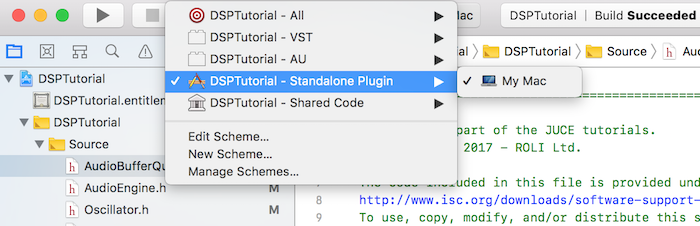
The project is conceived as a plugin but you can run it as a standalone application by selecting the proper deployment target in your IDE. In Xcode, you can change the target in the top left corner of the main window as shown in the following screenshot:
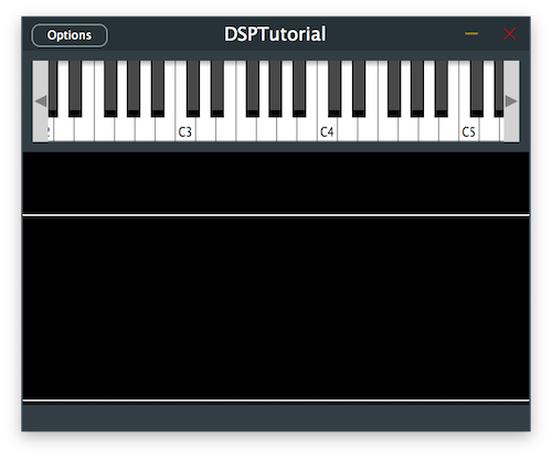
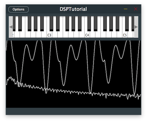
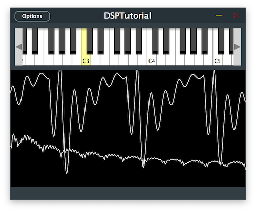
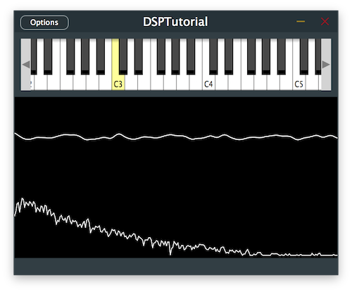
The demo project provides us with an on-screen MIDI keyboard in the top half of the plugin and a visual representation of the signal through an oscilloscope in the bottom half. Presently if a key is pressed, the plugin does not output any sound unless we provide an implementation of an oscillator.
Digital signal processing involves manipulating digital data to perform certain operations on the signal. In digital audio processing, we can deal with audio data in different domains:
A time or space domain signal can be converted to the frequency domain by using a transformation formula called the Fourier transform. A common efficient implementation of this transformation function is the Fast Fourier Transform or FFT, which you may encounter in the JUCE DSP module.
The FFT allows us to decompose an audio signal into its frequencies and represent the magnitude and phase information for each of these frequencies. Using its inverse function, we can revert the signal into its original domain thus making it really useful to process individual frequency components such as for filtering.
There are two main digital filter designs in dsp:
Within these filter designs, there are a number of different transfer functions that dictate the sharpness of the filter and the amount of ripples that occur at the transition frequency. Many of these designs are inspired by analog filters and different transfer functions try to emulate different analog counterparts.
Some of the transfer functions that you can find in the JUCE DSP module are:
If you are interested in these filter designs, you can find plenty of resources online that go more in depth about this topic but for the purpose of this tutorial, we have covered more than the basics to get us started.
Similarly to the audio application lifecycle of the AudioProcessor with its prepareToPlay() and getNextAudioBlock() functions, we have to implement the prepare() and renderNextBlock() functions of our AudioEngine class derived from MPESynthesiser.
Each dsp processor also has to implement the following methods to ensure proper functioning:
prepare(): called before the processing starts to set sample rate and block size.process(): processes the input and output buffers supplied in the processing context.reset(): resets the internal state of the processor with smoothing if necessary.A convenient template class of the DSP module is the juce::dsp::ProcessorChain which allows us to apply different processes in series by calling the prepare(), process() and reset() methods automatically one after the other.
We declare processors as template types like so:
We can then apply all our processes on the processorChain instance directly.
With some basic knowledge on how the dsp module works, let's start processing some signals!
In the CustomOscillator class, define a juce::dsp::ProcessorChain with juce::dsp::Oscillator and juce::dsp::Gain processors in this top-down order [1]. We want the gain processing to affect the output of the oscillator to be able to trim the level coming out. Also define an enum with processor indices [2] to be able to clearly refer to the corresponding process via its index later on.
In the prepare() function, call the prepare functions of each processor in the processor chain sequentially [3].
In the reset() function, call the reset functions of each processor in the processor chain sequentially [4].
Now we want to define the periodic function that the oscillator will use to generate the audio signal. As a simple example we will start with a sine wave.
In the constructor, get a reference to the Oscillator by supplying the index of the process and use the processorChain.get<>() method [5]. Let's initialise the oscillator using a lambda function and the std::sin function to provide the sine wave to the oscillator [6].
A lookup table will approximate expensive arithmetic operation depending on the number of supplied discrete points. In our case let's use 128 points.
To set the frequency of the oscillator, we need to once again get a reference to it similarly to the previous step and call the setFrequency() method on it [7].
Same process with the gain processor and its setGainLinear() method [8].
In the process() function, we can call the process functions of each processor in the processor chain sequentially [9].
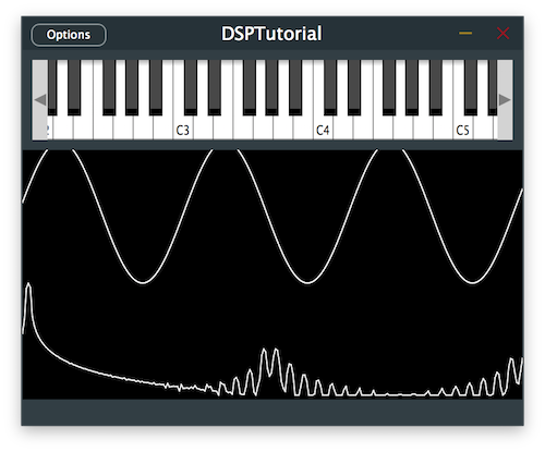
If we run this code after implementing the above changes in the CustomOscillator class, we should be able to hear a simple sine wave synthesiser using the JUCE DSP module.
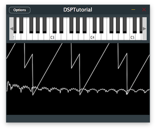
Let's make our synthesiser a little more exciting by changing its oscillator waveform to a sawtooth.
Since we do not have access to a std version of a sawtooth function, we need to implement a manual mapping of values using the jmap function. To do this, map the range between -Pi .. Pi to -1 .. 1 providing a linear ramp from -1 to 1. Since a sawtooth only has 2 breakpoints, we need only supply 2 discrete points to the lookup table.
Running the program should give us a different more aggressive sound.

Most analog synthesisers will have multiple oscillators and a common trick to get a thicker sound is to add a second oscillator with a slightly detuned frequency. So let's try that by modifying the Voice class.
Add a second CustomOscillator template type to the processor chain [1] and add its corresponding index in the enum [2].
Let's set the frequency of the second oscillator to the currently played note and pitch it up by 1% in the noteStarted() function [3]. We can keep the velocity at the same lavel as the first oscillator [4].
Let's make sure that the detuned frequency remains the same when pitch bend is applied in the notePitchbendChanged() function [5].
Let's run the program and see how it sounds like.
Let's introduce a filter design to our synthesiser. The ladder filter processor is inspired by a well-known analog design from the Moog synthesiser and this is the one we will use in our project. By now you should be familiar with the task of adding processors to the processor chain.
Add the juce::dsp::LadderFilter to the processor chain [1] and add its corresponding index to the enum [2] in the Voice class.
As previously explained, get the reference of the filter processor and set its cutoff frequency at 1kHz [3] and resonance at 0.7 [4].
The signal should now have its higher frequencies attenuated with a more muffled sound.
Now that we are getting closer to a classic analog synth sound, what more could there be? A modulating LFO of course.
A low frequency oscillator acts as a control signal to another parameter that we want to modulate. Its frequency is usually very low and is below the human hearing range therefore we should not add the oscillator in the processor chain like we did for the previous oscillators. This time, declare the new Oscillator as a regular member variable [1] in the Voice class.
To produce a slow and smooth modulation change to the cutoff frequency of the ladder filter, initialise the LFO as a sine wave [2] with a rate of 3Hz [3] in the Voice constructor.
Since we do not need to update the LFO as often as the audio processing sample rate, divide the sample rate by the LFO update rate to set the LFO sample rate in the prepare() function [4]. In this case we decide to update the LFO a hundred times less frequently.
In the following for() loop, we only modify the cutoff frequency every 100 samples. First call the processSample() function to process a single sample on the LFO [5] and then map its return value to the desired modulation range [6]. In this case we want to modulate the cutoff frequency from 100Hz to 2kHz. Finally, apply the new cutoff frequency to the ladder filter [7].
You should now hear a UFO-type siren sound.
At the moment if we play our synthesiser, you may have noticed that the sound is very dry so let's add a simple reverb to add depth to our signal. In order to apply the reverb to the entire synth sound, create an effects chain in the AudioEngine class and add the juce::dsp::Reverb template type to the effects chain [1] along with its index [2].
Call the prepare() function on the processor chain [3].
In order to process the effects chain, we need to retrieve the correct AudioBlock from the AudioBuffer to pass the context to the processing chain. First, convert the AudioBuffer to a usable AudioBlock [4] and refer to the right portion of the samples to manipulate using the getSubBlock() method [5]. Now we can get the processing context from this AudioBlock [6] and process the effects chain with it [7].
The synth should now have a smooth reverb tail added to the end of the signal.
DSPIntroductionTutorial_02.h file of the demo project.In this tutorial, we have learnt how to manipulate the audio buffer and process the signal using the JUCE DSP module. In particular, we have: