Loading...
Searching...
No Matches
Tutorial: Create a string model with delay lines

Implement a realistic string model by means of physical modelling. Incorporate a delay line to create intricate echo patterns in the stereo sound field.

Level: Advanced

Platforms: Windows, macOS, Linux

Plugin Format: VST, AU, Standalone

Classes: dsp::ProcessorChain, dsp::Gain, dsp::Oscillator, dsp::Convolution, dsp::WaveShaper, dsp::Reverb

Warning
This project requires a compiler that supports C++14 features. Recent versions of Xcode and Visual Studio include this support.

Getting started

This tutorial leads on from Tutorial: Add distortion through waveshaping and convolution. If you haven't done so already, you should read that tutorial first.

Download the demo project for this tutorial here: PIP | ZIP. Unzip the project and open the first header file in the Projucer.

Warning
If using the PIP version of this project, please make sure to copy the Resources folder into the generated Projucer project.

If you need help with this step, see Tutorial: Projucer Part 1: Getting started with the Projucer.

The demo project

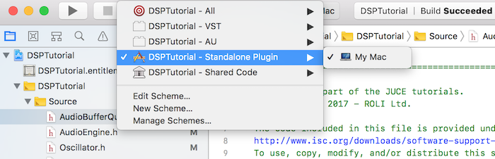
The project is conceived as a plugin but you can run it as a standalone application by selecting the proper deployment target in your IDE. In Xcode, you can change the target in the top left corner of the main window as shown in the following screenshot:

Changing the deployment target in Xcode

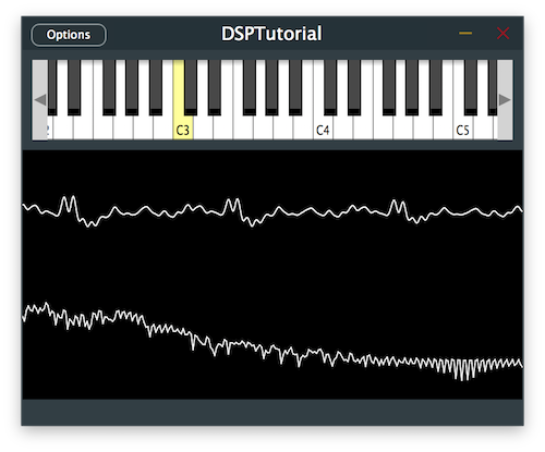
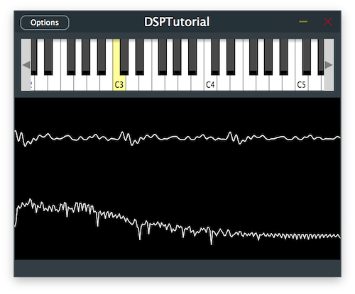
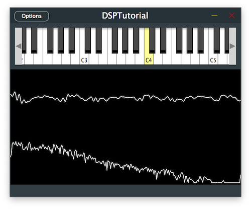
The demo project provides us with an on-screen MIDI keyboard in the top half of the plugin and a visual representation of the signal through an oscilloscope in the bottom half. Presently if a key is pressed, the plugin outputs a basic oscillator sound with some reverb and distortion added.

Note
Feel free to remove the effects to clearly hear the changes in each steps of the tutorial by commenting out the effects processors in the AudioEngine class.
The demo project plugin window
Note
If you have a MIDI controller, you can also choose to connect it instead of using the on-screen keyboard throughout this tutorial.

Introduction

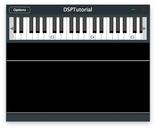
In this tutorial we are introducing two new DSP concepts that allow for signal processing in different ways: Delay Lines and Physical Modelling.

Let's start by defining this DSP terminology.

What is a Delay Line?

A delay line is a fundamental tool in DSP that can be used in a wide array of applications including simulations of reverberation spaces, sound synthesis, filter implementation and classic time-based effects such as delays, choruses, phasers and flangers.

Fundamentally, a delay line is very simple and allows us to delay a certain signal by a number of samples. By using multiple delay lines and summing the seperate signals back together at different intervals, we can create the vast majority of digital signal processing out there.

In the analog domain, delay lines were implemented by introducing an actual physical extension such as a spring to delay the propagation of waves. In the digital domain, delay lines are often implemented using a data structure referred to as a circular buffer.

A circular buffer can be essentially implemented as an array where the index wraps around itself in order to create a circular data structure that matches the size of the sample buffer block. This allows us to store all the samples included in the previous block to be accessed in the current block, only to be overwritten by the current sample block for the next iteration.

In this tutorial, we will look into circular buffers as a way to implement delay lines.

What is Physical Modelling?

Physical modelling denotes a sound synthesis method that relies on mathematical and physical models to generate sounds. Unlike other synthesis techniques, it does not make use of any samples as a starting point and focuses on how the sound is produced in the physical sense through the study of materials.

One of these models is called a digital waveguide which is based on the phyical model in which acoustic waves propagate through tubes or pipes. The reflection of these waves against boundaries can be efficiently computed using delay lines and as such many sounds of instruments such as strings can be generated using this model.

The waveguide string model

In a nutshell, the waveguide string model builds upon the notion that a vibrating string can be modelled using two waves that travel in opposite directions and bounce back at the two end points. The combination of these two waves summed together eventually simulates the ideal motion of a plucked string and these can be implemented using two delay lines: a forward and a backward delay line.

However, this ideal model of a string never comes to rest in its current state as damping is not taken into account. Thus when the waves change direction at the boundaries and their polarities are inversed we can incorporate a damping factor to reduce the displacement of the waves.

Other variables to consider in this model are where the plucking of the string should occur and where the sound of the vibrating string should be picked up from. We therefore have to integrate a plucking position from which the two waves will propagate and a pickup location just as you would listen to the sound from a specific location in space.

Last but not least, a natural phenomenon that occurs in physical strings is the faster decay of higher frequencies than lower frequencies. This can be easily integrated into our model by simply adding a low-pass filter at one end of the boundaries to simulate this discrepancy in decay times.

In this tutorial, we will implement this digital waveguide model by using delay lines to simulate plucked strings with waves that reflect at the boundaries of attached strings.

Implement a delay line

Let's start by implementing a simple delay line as a circular buffer using a vector.

In the DelayLine class, there are a couple of self-explanatory helper functions already defined to facilitate the implementation such as size() and resize() methods, a clear() function and a back() function that retrieves the least recent sample in the buffer.

We first implement the push() function which adds a new sample by overwriting the least recently added sample [1] and updates the least recent index variable by wrapping the index by the size of the circular buffer [2]:

void push (Type valueToAdd) noexcept
{
rawData[leastRecentIndex] = valueToAdd; // [1]
leastRecentIndex = leastRecentIndex == 0 ? size() - 1 : leastRecentIndex - 1; // [2]
}

Then we complete the get() function by returning the sample located at an offset specified by the function argument while making sure that the index wraps around the vector [3]. Notice here that we make sure the delay does not exceed the size of the buffer.

Type get (size_t delayInSamples) const noexcept
{
jassert (delayInSamples >= 0 && delayInSamples < size());
return rawData[(leastRecentIndex + 1 + delayInSamples) % size()]; // [3]
}

Next, we fill in the set() function by assigning the sample at an offset specified by the function argument while making sure that the index wraps around the vector [4]. Here again, we make sure the delay does not exceed the size of the buffer.

void set (size_t delayInSamples, Type newValue) noexcept
{
jassert (delayInSamples >= 0 && delayInSamples < size());
rawData[(leastRecentIndex + 1 + delayInSamples) % size()] = newValue; // [4]
}

And that completes our implementation of a simple delay line.

Incorporate a delay effect

With our basic delay line class implemented, let's incorporate a stereo delay effect into our signal chain.

In the Delay class, there are multiple parameters that can be tweaked to change the behaviour of our delay effect and these include delay times for individual channels, the maximum delay time allowed, the dry/wet level of the effect and the amount of feedback.

Using these parameters and the delay line implementation, we can create a wide range of delay effects as desired but let's start with the default parameters defined in the constructor:

{
public:
//==============================================================================
Delay()
{
setMaxDelayTime (2.0f);
setDelayTime (0, 0.7f);
setDelayTime (1, 0.5f);
setWetLevel (0.8f);
setFeedback (0.5f);
}

These helper functions mainly set the corresponding member variables to store the parameters but some of them also require a resizing of data structures to accomodate the parameter changes.

One such case is the setMaxDelayTime() function defined below which calls the updateDelayLineSize() helper function [1]:

void setMaxDelayTime (Type newValue)
{
jassert (newValue > Type (0));
maxDelayTime = newValue;
updateDelayLineSize(); // [1]
}

Complete the following function which ensures that the circular buffers of all the delay lines are large enough to accomodate any delay time up to the max delay time by resizing the vectors [2]:

void updateDelayLineSize()
{
auto delayLineSizeSamples = (size_t) std::ceil (maxDelayTime * sampleRate);
for (auto& dline : delayLines)
dline.resize (delayLineSizeSamples); // [2]
}

Another noteworthy case is in the setDelayTime() function of individual channels where a parameter change causes a call to the updateDelayTime() helper function [3] as follows:

void setDelayTime (size_t channel, Type newValue)
{
if (channel >= getNumChannels())
{
return;
}
jassert (newValue >= Type (0));
delayTimes[channel] = newValue;
updateDelayTime(); // [3]
}

Implement this helper function that recalculates the delay times in samples for all the channels based on the new parameter change [4]:

void updateDelayTime() noexcept
{
for (size_t ch = 0; ch < maxNumChannels; ++ch)
delayTimesSample[ch] = (size_t) juce::roundToInt (delayTimes[ch] * sampleRate);
}

In the reset() function, we reset the filters for each channel [5] which we will use in the next section of the tutorial and clear any old sample remaining in the delay lines [6]:

void reset() noexcept
{
for (auto& f : filters)
f.reset(); // [5]
for (auto& dline : delayLines)
dline.clear(); // [6]
}

In the prepare() function, we make sure that the size of the delay lines [7] and the delay times in samples [8] are still correct in case the sample rate was changed between sample blocks and initialise the filters with a low-pass filter for now [9]:

void prepare (const juce::dsp::ProcessSpec& spec)
{
jassert (spec.numChannels <= maxNumChannels);
sampleRate = (Type) spec.sampleRate;
updateDelayLineSize(); // [7]
updateDelayTime(); // [8]
filterCoefs = juce::dsp::IIR::Coefficients<Type>::makeFirstOrderLowPass (sampleRate, Type (1e3)); // [9]
for (auto& f : filters)
{
f.prepare (spec);
f.coefficients = filterCoefs;
}
}
#define jassert(expression)
Platform-independent assertion macro.
Definition juce_PlatformDefs.h:165

Now let's deal with the process() function to actually implement the delay effect:

template <typename ProcessContext>
void process (const ProcessContext& context) noexcept
{
auto& inputBlock = context.getInputBlock();
auto& outputBlock = context.getOutputBlock();
auto numSamples = outputBlock.getNumSamples();
auto numChannels = outputBlock.getNumChannels();
jassert (inputBlock.getNumSamples() == numSamples);
jassert (inputBlock.getNumChannels() == numChannels);
for (size_t ch = 0; ch < numChannels; ++ch)
{
auto* input = inputBlock .getChannelPointer (ch);
auto* output = outputBlock.getChannelPointer (ch);
auto& dline = delayLines[ch];
auto delayTime = delayTimesSample[ch];
auto& filter = filters[ch];
for (size_t i = 0; i < numSamples; ++i)
{
auto delayedSample = dline.get (delayTime); // [10]
auto inputSample = input[i]; // [11]
auto dlineInputSample = std::tanh (inputSample + feedback * delayedSample); // [12]
dline.push (dlineInputSample); // [13]
auto outputSample = inputSample + wetLevel * delayedSample; // [14]
output[i] = outputSample; // [15]
}
}
}
  • [10]: First, for each sample in the buffer block of each channel, retrieve the delayed sample from the corresponding delay line.
  • [11]: Then get the current sample from the input block.
  • [12]: Next, calculate the sample to be pushed into the delay line by mixing the input sample with the delay line output weighted with the feedback parameter using std::tanh(). The hyperbolic tangent function allows us to smoothly combine the two signals without clipping the summed sample and provides a natural decay.
  • [13]: We then push the sample calculated in the previous step into the delay line.
  • [14]: Finally, calculate the output sample by mixing the input sample with the delay line output weighted with the dry/wet parameter.
  • [15]: Then assign the sample to the output block.

If we run this code after implementing the above changes in the Delay class, we should be able to hear the delay effect on the oscillator signal.

Delaying the oscillator signal
Exercise
Experiment with different delay parameters and notice how the delay pattern evolves within the stereo field.

Filter the delay effect

Most delay effects incorporate a filtering of the signal as it repeats and decays in order to provide a more realistic sound just as it occurs in nature. So let's apply some filtering to the delayed sound.

This can be achieved very easily by simply changing one line in the process() function of the Delay class as follows:

template <typename ProcessContext>
void process (const ProcessContext& context) noexcept
{
//...
for (size_t ch = 0; ch < numChannels; ++ch)
{
//...
for (size_t i = 0; i < numSamples; ++i)
{
auto delayedSample = filter.processSample (dline.get (delayTime)); // [1]
auto inputSample = input[i];
auto dlineInputSample = std::tanh (inputSample + feedback * delayedSample);
dline.push (dlineInputSample);
auto outputSample = inputSample + wetLevel * delayedSample;
output[i] = outputSample;
}
}
}

Here we simply call the processSample() function on the filter object by passing the delayed sample from the delay line [1].

Change the filter type to a high-pass filter in the prepare() function by swapping the coefficients and calling the makeFirstOrderHighPass() function [2] as shown here:

void prepare (const juce::dsp::ProcessSpec& spec)
{
//...
filterCoefs = juce::dsp::IIR::Coefficients<Type>::makeFirstOrderHighPass (sampleRate, Type (1e3)); // [2]
//...
}

Running the program should give us a brighter delayed sound as the number of repeats increases.

Filtering the delayed signal
Exercise
Experiment with different types of filters to process the delayed sound and notice how the sound of the repeated signal changes.

Integrate a waveguide string model

Since we have conveniently implemented a delay line for our delay effect, we can use the same data structure to integrate a waveguide string model using the same class.

In the WaveguideString class, there are multiple parameters that can be tweaked to change the behaviour of our string model and these include the trigger position, the pickup position and the decay time for the damping of the strings.

Default parameters are defined in the constructor which in turn set the corresponding member variables as follows:

public:
//==============================================================================
WaveguideString()
{
setTriggerPosition (Type (0.2));
setPickupPosition (Type (0.8));
setDecayTime (Type (0.5));
}

These helper functions also call the updateParameters() function which initialises various variables such as the size of the delay lines, the pickup indices relative to the delay lines, the trigger index relative to the forward delay line and the filter coefficients as well as the decay coefficient based on the decay time.

Add the implementation of this helper function as described below:

void updateParameters()
{
auto length = (size_t) juce::roundToInt (sampleRateHz / freqHz); // [1]
forwardDelayLine .resize (length);
backwardDelayLine.resize (length);
forwardPickupIndex = (size_t) juce::roundToInt (jmap (pickupPos, Type (0), Type (length / 2 - 1))); // [2]
backwardPickupIndex = length - 1 - forwardPickupIndex;
forwardTriggerIndex = (size_t) juce::roundToInt (jmap (triggerPos, Type (0), Type (length / 2 - 1))); // [3]
filter.coefficients = juce::dsp::IIR::Coefficients<Type>::makeFirstOrderLowPass (sampleRateHz, 4 * freqHz); // [4]
decayCoef = juce::jmap (decayTime, std::pow (Type (0.999), Type (length)), std::pow (Type (0.99999), Type (length))); // [5]
reset();
}
constexpr Type jmap(Type value0To1, Type targetRangeMin, Type targetRangeMax)
Remaps a normalised value (between 0 and 1) to a target range.
Definition juce_MathsFunctions.h:369
  • [1]: First, we resize the delay lines to the sample rate over the fundamental frequency of the note played. This is taken from the fact that the fundamental frequency is equal to the sampling frequency over the number of samples needed in the loop.
  • [2]: Next, we retrieve the index of the pickup position on the forward delay line by mapping the variable in the range of 0.0 .. 1.0 to the range of 0 to half of the delay line length. This is to accomodate the full cycle which includes the two directions of the travelling wave with the polarity flipping. The index of the pickup position on the backward delay line is calculated by simply taking the inverse of the forward index.
  • [3]: The index of the trigger position on the forward delay line is mapped in the same way from the range of 0.0 .. 1.0 to the range of 0 to half of the delay line length.
  • [4]: Then the coefficients of the low-pass filter that simulates the decay behaviour are set at a frequency that is four times higher than its fundamental.
  • [5]: Finally, the decay coefficient is calculated from the decay time by mapping from the range of 0.0 .. 1.0 to the range of 0.999^length to 0.99999^length. This produces values close to 1 which depicts the very little damping that actually happens on physical vibrating strings.

In the reset() function, we reset the delay lines to clear any old sample remaining:

void reset() noexcept
{
forwardDelayLine .clear();
backwardDelayLine.clear();
}

In the prepare() function, we create a temporary audio block that will be used later for processing [6] and make sure that the parameters are still correct in case the sample rate was changed between sample blocks by calling the updateParameters() function again [7]:

void prepare (const juce::dsp::ProcessSpec& spec)
{
sampleRateHz = (Type) spec.sampleRate;
tempBlock = juce::dsp::AudioBlock<float> (heapBlock, spec.numChannels, spec.maximumBlockSize); // [6]
filter.prepare (spec);
updateParameters(); // [7]
}

To trigger the excitation of the string provoked by the plucking, we have to set the initial displacement of both waves represented by the two delay lines.

To do this in the trigger() function, iterate first between the samples contained from the start of the delay line to the index of the trigger position, calculate the values for each sample by mapping the indices to ascending values reaching half of the note velocity and assigning these to the delay lines in opposite directions [8]. Do the same for the samples contained between the index of the trigger position to the end of the delay line with descending values from half of the note velocity [9].

void trigger (Type velocity) noexcept
{
jassert (velocity >= Type (0) && velocity <= Type (1));
for (size_t i = 0; i <= forwardTriggerIndex; ++i) // [8]
{
auto value = juce::jmap (Type (i), Type (0), Type (forwardTriggerIndex), Type (0), velocity / 2);
forwardDelayLine .set (i, value);
backwardDelayLine.set (getDelayLineLength() - 1 - i, value);
}
for (size_t i = forwardTriggerIndex; i < getDelayLineLength(); ++i) // [9]
{
auto value = juce::jmap (Type (i), Type (forwardTriggerIndex), Type (getDelayLineLength() - 1), velocity / 2, Type (0));
forwardDelayLine .set (i, value);
backwardDelayLine.set (getDelayLineLength() - 1 - i, value);
}
}

To generate all the samples in a buffer block, we declare a helper function that returns only one iteration of sample generation as follows:

Type processSample() noexcept
{
auto forwardOut = forwardDelayLine .back(); // [10]
auto backwardOut = backwardDelayLine.back(); // [11]
forwardDelayLine .push (-backwardOut); // [12]
backwardDelayLine.push (-decayCoef * filter.processSample (forwardOut)); // [13]
return forwardDelayLine.get (forwardPickupIndex) + backwardDelayLine.get (backwardPickupIndex); // [14]
}
  • [10]: First, we retrieve the least recent sample from the circular buffer of the forward delay line by calling the back() function declared earlier.
  • [11]: We do the same for the least recent sample of the backward delay line.
  • [12]: Next, we have to push this last sample located at the boundary of the backward delay line into the forward delay line by inverting the polarity.
  • [13]: Then, we do the same for the other delay line but this time instead we filter the sample with the low-pass filter and multiply by the decay coefficient to apply dampening before inverting the polarity and pushing the sample into the circular buffer.
  • [14]: Finally, we return the recorded sample from the pickup location by summing the signal from both delay lines at their respective pickup indices.

In the process() function, simply process all the samples in the buffer block by calling the processSample() helper function and assigning the values to the temporary block created earlier [15]. Then copy the samples to all channels in the audio block [16] and add the content of the temporary block into the output block along with the original content contained in the input block [17].

template <typename ProcessContext>
void process (const ProcessContext& context) noexcept
{
auto&& outBlock = context.getOutputBlock();
auto numSamples = outBlock.getNumSamples();
auto* dst = tempBlock.getChannelPointer (0);
for (size_t i = 0; i < numSamples; ++i) // [15]
dst[i] = processSample();
for (size_t ch = 1; ch < tempBlock.getNumChannels(); ++ch) // [16]
juce::FloatVectorOperations::copy (tempBlock.getChannelPointer (ch),
tempBlock.getChannelPointer (0),
(int) numSamples);
outBlock.copyFrom (context.getInputBlock()).add (tempBlock.getSubBlock (0, outBlock.getNumSamples()));
}

In the Voice class, add a WaveguideString processor to the processor chain [18] and add its corresponding index in the enum [19].

enum
{
oscIndex,
stringIndex, // [19]
masterGainIndex
};
juce::dsp::ProcessorChain<CustomOscillator<float>, WaveguideString<float>, juce::dsp::Gain<float>> processorChain; // [18]
};

In the noteStarted() function, remove the line that sets the level of the oscillator as we will be using the waveguide string model to generate sounds. Retrieve a reference to the string model from the processor chain [20], set the fundamental frequency of the string to the frequency of the note played [21] and trigger the plucking by calling the trigger() function with the note velocity [22].

void noteStarted() override
{
auto velocity = getCurrentlyPlayingNote().noteOnVelocity.asUnsignedFloat();
auto freqHz = (float) getCurrentlyPlayingNote().getFrequencyInHertz();
processorChain.get<oscIndex>().setFrequency (freqHz, true);
//processorChain.get<oscIndex>().setLevel (velocity);
auto& stringModel = processorChain.get<stringIndex>(); // [20]
stringModel.setFrequency (freqHz); // [21]
stringModel.trigger (velocity); // [22]
}

Let's run the program and see how it sounds like.

Delaying the waveguide string signal
Exercise
Experiment with different waveguide parameters such as pickup/trigger positions and decay time as well as filter types and notice how it affects the generated string sound.
Note
The source code for this modified version of the code can be found in the DSPDelayLineTutorial_02.h file of the demo project.

Summary

In this tutorial, we have learnt how to implement a string model and a delay line. In particular, we have:

  • Learnt the basics of physical modelling and delay lines.
  • Implemented a delay line used as the basis for simple time-based effects.
  • Incorporated the delay line to create an interesting delay effect in stereo.
  • Integrated a waveguide string model based on physical modelling techniques.
Note
Return to part 1 of this tutorial to brush up on oscillators and filters here: Tutorial: Introduction to DSP
Jump back to part 2 of this tutorial to understand distortion and convolution here: Tutorial: Add distortion through waveshaping and convolution

See also

linkedin facebook pinterest youtube rss twitter instagram facebook-blank rss-blank linkedin-blank pinterest youtube twitter instagram