Loading...
Searching...
No Matches
Tutorial: Cascading plug-in effects

Create your own channel strip by learning how to daisy chain audio processors or plugins using an AudioProcessorGraph. Learn how to use the AudioProcessorGraph in both a plugin and standalone application context.

Level: Intermediate

Platforms: Windows, macOS, Linux

Classes: AudioProcessor, AudioProcessorPlayer, AudioProcessorGraph, AudioProcessorGraph::AudioGraphIOProcessor, AudioProcessorGraph::Node, AudioDeviceManager

Getting started

Download the demo project for this tutorial here: PIP | ZIP. Unzip the project and open the first header file in the Projucer.

If you need help with this step, see Tutorial: Projucer Part 1: Getting started with the Projucer.

The demo project

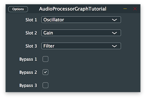
The demo project simulates a channel strip where different audio processors can be applied in series. There are three available slots that can be individually bypassed and three different processors including an oscillator, a gain control and a filter that can be chosen from. The plugin applies processing on incoming audio and propagates the modified signal to the output.

The channel strip plugin window

Setting up the AudioProcessorGraph

The AudioProcessorGraph is a special type of AudioProcessor that allows us to connect several AudioProcessor objects together as nodes in a graph and play back the result of the combined processing. In order to wire-up graph nodes together, we have to add connections between channels of nodes in the order we wish to process the audio signal.

The AudioProcessorGraph class also offers special node types for input and output handling of audio and midi signals within the graph. An example graph of the channel strip would look something like this when connected properly:

Let's start by setting up the main AudioProcessorGraph to receive incoming signals and send them back to the corresponding output unprocessed.

In order to reduce the character count for nested classes used frequently in this tutorial, we first declare a using for the AudioGraphIOProcessor class and the Node class in the TutorialProcessor class as follows:

using AudioGraphIOProcessor = juce::AudioProcessorGraph::AudioGraphIOProcessor;
using Node = juce::AudioProcessorGraph::Node;

Then we declare the following private member variables using the shortened version of class names like so:

Node::Ptr audioInputNode;
Node::Ptr audioOutputNode;
Node::Ptr midiInputNode;
Node::Ptr midiOutputNode;

Here we create pointers to the main AudioProcessorGraph as well as the input and output processor nodes which will be instantiated later on within the graph.

Next, in the TutorialProcessor contructor we set the default bus properties for the plugin and instantiate the main AudioProcessorGraph as shown here:

TutorialProcessor()
: AudioProcessor (BusesProperties().withInput ("Input", juce::AudioChannelSet::stereo(), true)
.withOutput ("Output", juce::AudioChannelSet::stereo(), true)),
mainProcessor (new juce::AudioProcessorGraph()),

Since we are dealing with a plugin, we need to implement the isBusesLayoutSupported() callback to inform the plugin host or DAW about which channel sets we support. In this example we decide to only support mono-to-mono and stereo-to-stereo configurations like this:

bool isBusesLayoutSupported (const BusesLayout& layouts) const override
{
if (layouts.getMainInputChannelSet() == juce::AudioChannelSet::disabled()
|| layouts.getMainOutputChannelSet() == juce::AudioChannelSet::disabled())
return false;
if (layouts.getMainOutputChannelSet() != juce::AudioChannelSet::mono()
&& layouts.getMainOutputChannelSet() != juce::AudioChannelSet::stereo())
return false;
return layouts.getMainInputChannelSet() == layouts.getMainOutputChannelSet();
}
Note
If you want to learn more about bus layouts of plugins, please refer to Tutorial: Configuring the right bus layouts for your plugins.

For the TutorialProcessor to be able to process audio through the graph provided, we have to override the three main functions of the AudioProcessor class that perform signal processing namely the prepareToPlay(), releaseResources() and processBlock() functions and call the same respective functions on the AudioProcessorGraph.

Let's start with the prepareToPlay() function. First we inform the AudioProcessorGraph on the number of I/O channels, the sample rate and the number of samples per block by calling the setPlayConfigDetails() function like follows:

void prepareToPlay (double sampleRate, int samplesPerBlock) override
{
mainProcessor->setPlayConfigDetails (getMainBusNumInputChannels(),
getMainBusNumOutputChannels(),
sampleRate, samplesPerBlock);
mainProcessor->prepareToPlay (sampleRate, samplesPerBlock);
initialiseGraph();
}

We then call the prepareToPlay() function on the AudioProcessorGraph with the same information and call the initialiseGraph() helper function which we define later on to create and connect the nodes in the graph.

The releaseResources() function is self-explanatory and simply calls the same function on the AudioProcessorGraph instance:

void releaseResources() override
{
mainProcessor->releaseResources();
}

Finally in the processBlock() function, we clear the samples contained in any additional channels that may contain garbage data just in case and call the updateGraph() helper function later defined that will rebuild the graph if the channel strip configuration was changed. The processBlock() function is eventually called on the AudioProcessorGraph at the end of the function:

void processBlock (juce::AudioSampleBuffer& buffer, juce::MidiBuffer& midiMessages) override
{
for (int i = getTotalNumInputChannels(); i < getTotalNumOutputChannels(); ++i)
buffer.clear (i, 0, buffer.getNumSamples());
updateGraph();
mainProcessor->processBlock (buffer, midiMessages);
}

The initialiseGraph() function called earlier in the prepareToPlay() callback starts by clearing the AudioProcessorGraph of any nodes and connections that were previously present. This also takes care of deleting the corresponding AudioProcessor instances associated to the deleted nodes in the graph. We then proceed to instantiate the AudioGraphIOProcessor objects for the graph I/O and add the AudioProcessor objects as nodes in the graph.

void initialiseGraph()
{
mainProcessor->clear();
audioInputNode = mainProcessor->addNode (std::make_unique<AudioGraphIOProcessor> (AudioGraphIOProcessor::audioInputNode));
audioOutputNode = mainProcessor->addNode (std::make_unique<AudioGraphIOProcessor> (AudioGraphIOProcessor::audioOutputNode));
midiInputNode = mainProcessor->addNode (std::make_unique<AudioGraphIOProcessor> (AudioGraphIOProcessor::midiInputNode));
midiOutputNode = mainProcessor->addNode (std::make_unique<AudioGraphIOProcessor> (AudioGraphIOProcessor::midiOutputNode));
connectAudioNodes();
connectMidiNodes();
}

We still have to add connections between the newly-created nodes in the graph to propagate the audio/midi data and this is performed with the following helper functions:

void connectAudioNodes()
{
for (int channel = 0; channel < 2; ++channel)
mainProcessor->addConnection ({ { audioInputNode->nodeID, channel },
{ audioOutputNode->nodeID, channel } });
}

Here we call the addConnection() function on the AudioProcessorGraph instance by passing the source and destination nodes we wish to connect in the form of a Connection object. These require a nodeID and a channel index for building the appropriate connections and the whole process is repeated for all the required channels.

void connectMidiNodes()
{
mainProcessor->addConnection ({ { midiInputNode->nodeID, juce::AudioProcessorGraph::midiChannelIndex },
{ midiOutputNode->nodeID, juce::AudioProcessorGraph::midiChannelIndex } });
}

The same is performed on the midi I/O nodes with the exception of the channel index argument. Since the midi signals are not sent through regular audio channels, we have to supply a special channel index specified as an enum in the AudioProcessorGraph class.

At this stage of the tutorial, we should be able to hear the signal pass through the graph without being altered.

Warning
Beware of screaming feedback when testing the plugin with built-in inputs and outputs. You can avoid this problem by using headphones.

Implementing different processors

In this part of the tutorial, we create different processors that we can use within our channel strip plugin to alter the incoming audio signal. Feel free to create additional processors or customise the following ones to your taste.

In order to avoid repeated code for the different processors we want to create, let's start by declaring an AudioProcessor base class that will be inherited by the individual processors and override the necessary functions only once for simplicity's sake.

class ProcessorBase : public juce::AudioProcessor
{
public:
//==============================================================================
ProcessorBase()
: AudioProcessor (BusesProperties().withInput ("Input", juce::AudioChannelSet::stereo())
.withOutput ("Output", juce::AudioChannelSet::stereo()))
{}
//==============================================================================
void prepareToPlay (double, int) override {}
void releaseResources() override {}
void processBlock (juce::AudioSampleBuffer&, juce::MidiBuffer&) override {}
//==============================================================================
juce::AudioProcessorEditor* createEditor() override { return nullptr; }
bool hasEditor() const override { return false; }
//==============================================================================
const juce::String getName() const override { return {}; }
bool acceptsMidi() const override { return false; }
bool producesMidi() const override { return false; }
double getTailLengthSeconds() const override { return 0; }
//==============================================================================
int getNumPrograms() override { return 0; }
int getCurrentProgram() override { return 0; }
void setCurrentProgram (int) override {}
const juce::String getProgramName (int) override { return {}; }
void changeProgramName (int, const juce::String&) override {}
//==============================================================================
void getStateInformation (juce::MemoryBlock&) override {}
void setStateInformation (const void*, int) override {}
private:
//==============================================================================
};
Note
The following three processors will make use of the DSP module to facilitate implementation and if you want to learn more about DSP you can refer to Tutorial: Introduction to DSP for a more in-depth explanation.

Implementing an oscillator

The first processor is a simple oscillator that generates a constant sine wave tone at 440Hz.

We derive the OscillatorProcessor class from the previously-defined ProcessorBase, override the getName() function to provide a meaningful name and declare a dsp::Oscillator object from the DSP module:

class OscillatorProcessor : public ProcessorBase
{
public:
//...
const juce::String getName() const override { return "Oscillator"; }
private:
juce::dsp::Oscillator<float> oscillator;
};

In the constructor, we set the frequency and the waveform of the oscillator by calling respectively the setFrequency() and initialise() functions on the dsp::Oscillator object as follows:

OscillatorProcessor()
{
oscillator.setFrequency (440.0f);
oscillator.initialise ([] (float x) { return std::sin (x); });
}

In the prepareToPlay() function, we create a dsp::ProcessSpec object to describe the sample rate and number of samples per block to the dsp::Oscillator object and pass the specifications by calling the prepare() function on it like so:

void prepareToPlay (double sampleRate, int samplesPerBlock) override
{
juce::dsp::ProcessSpec spec { sampleRate, static_cast<juce::uint32> (samplesPerBlock), 2 };
oscillator.prepare (spec);
}

Next, in the processBlock() function we create a dsp::AudioBlock object from the AudioSampleBuffer passed as an argument and declare the processing context from it as a dsp::ProcessContextReplacing object that is subsequently passed to the process() function of the dsp::Oscillator object as shown here:

void processBlock (juce::AudioSampleBuffer& buffer, juce::MidiBuffer&) override
{
juce::dsp::AudioBlock<float> block (buffer);
juce::dsp::ProcessContextReplacing<float> context (block);
oscillator.process (context);
}

Finally, we can reset the state of the dsp::Oscillator object by overriding the reset() function of the AudioProcessor and calling the same function onto it:

void reset() override
{
oscillator.reset();
}

We now have an oscillator that we can use in our channel strip plugin.

Exercise
Modify the initialise() function of the oscillator to produce a different waveform and change the target frequency.

Implementing a gain control

The second processor is a simple gain control that attenuates the incoming signal by -6dB.

We derive the GainProcessor class from the previously-defined ProcessorBase, override the getName() function to provide a meaningful name and declare a dsp::Gain object from the DSP module:

class GainProcessor : public ProcessorBase
{
public:
//...
const juce::String getName() const override { return "Gain"; }
private:
juce::dsp::Gain<float> gain;
};

In the constructor, we set the gain in decibels of the gain control by calling the setGainDecibels() function on the dsp::Gain object as follows:

GainProcessor()
{
gain.setGainDecibels (-6.0f);
}

In the prepareToPlay() function, we create a dsp::ProcessSpec object to describe the sample rate, number of samples per block and number of channels to the dsp::Gain object and pass the specifications by calling the prepare() function on it like so:

void prepareToPlay (double sampleRate, int samplesPerBlock) override
{
juce::dsp::ProcessSpec spec { sampleRate, static_cast<juce::uint32> (samplesPerBlock), 2 };
gain.prepare (spec);
}

Next, in the processBlock() function we create a dsp::AudioBlock object from the AudioSampleBuffer passed as an argument and declare the processing context from it as a dsp::ProcessContextReplacing object that is subsequently passed to the process() function of the dsp::Gain object as shown here:

void processBlock (juce::AudioSampleBuffer& buffer, juce::MidiBuffer&) override
{
juce::dsp::AudioBlock<float> block (buffer);
juce::dsp::ProcessContextReplacing<float> context (block);
gain.process (context);
}

Finally, we can reset the state of the dsp::Gain object by overriding the reset() function of the AudioProcessor and calling the same function onto it:

void reset() override
{
gain.reset();
}

We now have a gain control that we can use in our channel strip plugin.

Exercise
Modify the setGainDecibels() function of the gain control to reduce the gain furthermore or boost the signal. (Careful with levels when boosting!)

Implementing a filter

The third processor is a simple high pass filter that reduces the frequencies below 1kHz.

We derive the FilterProcessor class from the previously-defined ProcessorBase, override the getName() function to provide a meaningful name and declare a dsp::ProcessorDuplicator object from the DSP module. This allows us to use a mono processor of the dsp::IIR::Filter class and convert it into a multi-channel version by providing its shared state as a dsp::IIR::Coefficients class:

class FilterProcessor : public ProcessorBase
{
public:
FilterProcessor() {}
//...
const juce::String getName() const override { return "Filter"; }
private:
juce::dsp::ProcessorDuplicator<juce::dsp::IIR::Filter<float>, juce::dsp::IIR::Coefficients<float>> filter;
};

In the prepareToPlay() function, we first generate the coefficients used for the filter by using the makeHighPass() function and assign it as the shared processing state to the duplicator. We then create a dsp::ProcessSpec object to describe the sample rate, number of samples per block and number of channels to the dsp::ProcessorDuplicator object and pass the specifications by calling the prepare() function on it like so:

void prepareToPlay (double sampleRate, int samplesPerBlock) override
{
*filter.state = *juce::dsp::IIR::Coefficients<float>::makeHighPass (sampleRate, 1000.0f);
juce::dsp::ProcessSpec spec { sampleRate, static_cast<juce::uint32> (samplesPerBlock), 2 };
filter.prepare (spec);
}

Next, in the processBlock() function we create a dsp::AudioBlock object from the AudioSampleBuffer passed as an argument and declare the processing context from it as a dsp::ProcessContextReplacing object that is subsequently passed to the process() function of the dsp::ProcessorDuplicator object as shown here:

void processBlock (juce::AudioSampleBuffer& buffer, juce::MidiBuffer&) override
{
juce::dsp::AudioBlock<float> block (buffer);
juce::dsp::ProcessContextReplacing<float> context (block);
filter.process (context);
}

Finally, we can reset the state of the dsp::ProcessorDuplicator object by overriding the reset() function of the AudioProcessor and calling the same function onto it:

void reset() override
{
filter.reset();
}

We now have a filter that we can use in our channel strip plugin.

Exercise
Modify the coefficients of the filter to produce a low pass or band pass filter with different cut-off frequencies and resonance.

Connecting graph nodes together

Now that we have implemented multiple processors that can be used within the AudioProcessorGraph, let's start connecting them together depending on the user selection.

In the TutorialProcessor class, we add three AudioParameterChoice and four AudioParameterBool pointers as private member variables to store the parameters chosen in the channel strip and their corresponding bypass states. We also declare node pointers to the three processor slots when later instantiated within the graph and provide the selectable choices as a StringArray for convenience.

juce::StringArray processorChoices { "Empty", "Oscillator", "Gain", "Filter" };
std::unique_ptr<juce::AudioProcessorGraph> mainProcessor;
juce::AudioParameterBool* muteInput;
juce::AudioParameterChoice* processorSlot1;
juce::AudioParameterChoice* processorSlot2;
juce::AudioParameterChoice* processorSlot3;
juce::AudioParameterBool* bypassSlot1;
juce::AudioParameterBool* bypassSlot2;
juce::AudioParameterBool* bypassSlot3;
Node::Ptr audioInputNode;
Node::Ptr audioOutputNode;
Node::Ptr midiInputNode;
Node::Ptr midiOutputNode;
Node::Ptr slot1Node;
Node::Ptr slot2Node;
Node::Ptr slot3Node;
//==============================================================================
};

Then in the constructor we can instantiate the audio parameters and call the addParameter() function to tell the AudioProcessor about which parameters should be available in the plugin.

TutorialProcessor()
: AudioProcessor (BusesProperties().withInput ("Input", juce::AudioChannelSet::stereo(), true)
.withOutput ("Output", juce::AudioChannelSet::stereo(), true)),
mainProcessor (new juce::AudioProcessorGraph()),
muteInput (new juce::AudioParameterBool ("mute", "Mute Input", true)),
processorSlot1 (new juce::AudioParameterChoice ("slot1", "Slot 1", processorChoices, 0)),
processorSlot2 (new juce::AudioParameterChoice ("slot2", "Slot 2", processorChoices, 0)),
processorSlot3 (new juce::AudioParameterChoice ("slot3", "Slot 3", processorChoices, 0)),
bypassSlot1 (new juce::AudioParameterBool ("bypass1", "Bypass 1", false)),
bypassSlot2 (new juce::AudioParameterBool ("bypass2", "Bypass 2", false)),
bypassSlot3 (new juce::AudioParameterBool ("bypass3", "Bypass 3", false))
{
addParameter (muteInput);
addParameter (processorSlot1);
addParameter (processorSlot2);
addParameter (processorSlot3);
addParameter (bypassSlot1);
addParameter (bypassSlot2);
addParameter (bypassSlot3);
}

This tutorial makes use of the GenericAudioProcessorEditor class, which automatically creates a ComboBox for each of the parameters in the plug-in's processor that is an AudioParameterChoice type and a ToggleButton for each AudioParameterBool type.

Note
To learn more about audio parameters and how to customise them, please refer to Tutorial: Adding plug-in parameters. For a more seamless and elegant method for saving and loading parameters, you can take a look at Tutorial: Saving and loading your plug-in state.

In the first part of the tutorial when setting up the AudioProcessorGraph, we noticed that we call the updateGraph() helper function in the processBlock() callback of the TutorialProcessor class. The purpose of this function is to update the graph by reinstantiating the proper AudioProcessor objects and nodes as well as reconnecting the graph depending on the current choices selected by the user so let's implement that helper function like this:

void updateGraph()
{
bool hasChanged = false;
juce::Array<juce::AudioParameterChoice*> choices { processorSlot1,
processorSlot2,
processorSlot3 };
juce::Array<juce::AudioParameterBool*> bypasses { bypassSlot1,
bypassSlot2,
bypassSlot3 };
juce::ReferenceCountedArray<Node> slots;
slots.add (slot1Node);
slots.add (slot2Node);
slots.add (slot3Node);

The function starts by declaring a local variable representing the state of the graph and whether it has changed since the last iteration of the audio block processing. It also creates arrays to facilitate iteration over the processor choices, bypass states and their corresponding nodes in the graph.

In the next part, we iterate over the three available processor slots and check the options that were selected for each of the AudioParameterChoice objects as follows:

for (int i = 0; i < 3; ++i)
{
auto& choice = choices.getReference (i);
auto slot = slots .getUnchecked (i);
if (choice->getIndex() == 0) // [1]
{
if (slot != nullptr)
{
mainProcessor->removeNode (slot.get());
slots.set (i, nullptr);
hasChanged = true;
}
}
else if (choice->getIndex() == 1) // [2]
{
if (slot != nullptr)
{
if (slot->getProcessor()->getName() == "Oscillator")
continue;
mainProcessor->removeNode (slot.get());
}
slots.set (i, mainProcessor->addNode (std::make_unique<OscillatorProcessor>()));
hasChanged = true;
}
else if (choice->getIndex() == 2) // [3]
{
if (slot != nullptr)
{
if (slot->getProcessor()->getName() == "Gain")
continue;
mainProcessor->removeNode (slot.get());
}
slots.set (i, mainProcessor->addNode (std::make_unique<GainProcessor>()));
hasChanged = true;
}
else if (choice->getIndex() == 3) // [4]
{
if (slot != nullptr)
{
if (slot->getProcessor()->getName() == "Filter")
continue;
mainProcessor->removeNode (slot.get());
}
slots.set (i, mainProcessor->addNode (std::make_unique<FilterProcessor>()));
hasChanged = true;
}
}
  • [1]: If the choice remains in the "Empty" state, we first check whether the node was previously instantiated to a different processor and if so, we remove the node from the graph, clear the reference to the node and set the hasChanged flag to true. Otherwise, the state has not changed and the graph does not need rebuilding.
  • [2]: If the user chooses the "Oscillator" state, we first check whether the currently instantiated node is already an oscillator processor and if so, the state has not changed and we continue onto the next slot. Otherwise, if the slot was already occupied we remove the node from the graph, set the reference to a new node by instantiating the oscillator and set the hasChanged flag to true.
  • [3]: We proceed to do the same for the "Gain" state and instantiate a gain processor if necessary.
  • [4]: Again, we repeat the same process for the "Filter" state and instantiate a filter processor if needed.

The next section is only performed if the state of the graph has changed and we start connecting the nodes as follows:

if (hasChanged)
{
for (auto connection : mainProcessor->getConnections()) // [5]
mainProcessor->removeConnection (connection);
juce::ReferenceCountedArray<Node> activeSlots;
for (auto slot : slots)
{
if (slot != nullptr)
{
activeSlots.add (slot); // [6]
slot->getProcessor()->setPlayConfigDetails (getMainBusNumInputChannels(),
getMainBusNumOutputChannels(),
getSampleRate(), getBlockSize());
}
}
if (activeSlots.isEmpty()) // [7]
{
connectAudioNodes();
}
else
{
for (int i = 0; i < activeSlots.size() - 1; ++i) // [8]
{
for (int channel = 0; channel < 2; ++channel)
mainProcessor->addConnection ({ { activeSlots.getUnchecked (i)->nodeID, channel },
{ activeSlots.getUnchecked (i + 1)->nodeID, channel } });
}
for (int channel = 0; channel < 2; ++channel) // [9]
{
mainProcessor->addConnection ({ { audioInputNode->nodeID, channel },
{ activeSlots.getFirst()->nodeID, channel } });
mainProcessor->addConnection ({ { activeSlots.getLast()->nodeID, channel },
{ audioOutputNode->nodeID, channel } });
}
}
connectMidiNodes();
for (auto node : mainProcessor->getNodes()) // [10]
node->getProcessor()->enableAllBuses();
}
  • [5]: First we remove all the connections in the graph to start from a blank state.
  • [6]: Then, we iterate over the slots and check whether they have an AudioProcessor node within the graph. If so we add the node to our temporary array of active nodes and make sure to call the setPlayConfigDetails() function on the corresponding processor instance with channel, sample rate and block size information to prepare the node for future processing.
  • [7]: Next, if there are no active slots found this means that all the choices are in an "Empty" state and the audio I/O processor nodes can be simply connected together.
  • [8]: Otherwise, it means that there is at least one node that should lie between the audio I/O processor nodes. Therefore we can start connecting the active slots together in an ascending order of slot number. Notice here that the number of pairs of connections we need is only the number of active slots minus one.
  • [9]: We can then finish connecting the graph by linking the audio input processor node to the first active slot in the chain and the last active slot to the audio output processor node.
  • [10]: Finally, we connect the midi I/O nodes together and make sure that all the buses in the audio processors are enabled.
for (int i = 0; i < 3; ++i)
{
auto slot = slots .getUnchecked (i);
auto& bypass = bypasses.getReference (i);
if (slot != nullptr)
slot->setBypassed (bypass->get());
}
audioInputNode->setBypassed (muteInput->get());
slot1Node = slots.getUnchecked (0);
slot2Node = slots.getUnchecked (1);
slot3Node = slots.getUnchecked (2);
}

In the last section of the updateGraph() helper function, we deal with the bypass state of the processors by checking whether the slot is active and bypass the AudioProcessor if the check box is toggled. We also check whether to mute the input to avoid feedback loops when testing. Then, we assign back the newly-created nodes to their corresponding slots for the next iteration.

The plugin should now run by processing incoming audio through the loaded processors within the graph.

Exercise
Create an additional processor node of your choice and add it to the AudioProcessorGraph. (For example a processor handling midi messages.)

Convert the plugin into an application

If you are interested in using the AudioProcessorGraph within a standalone app, this optional section will delve into this in detail.

First of all, we have to convert our main TutorialProcessor class into a subclass of Component instead of AudioProcessor. To match the naming convention of other JUCE GUI applications we also rename the class name to MainComponent as follows:

class MainComponent : public juce::Component,
private juce::Timer
{
public:
Note
If using a PIP file to follow this tutorial, make sure to change the "mainClass" and "type" fields to reflect the change and amend the "dependencies" field appropriately. If using the ZIP version of the project, make sure that the Main.cpp file follows the "GUI Application" template format.

When creating a plugin, all the IO device management and playback functionalities are controlled by the host and therefore we don't need to worry about setting these up. However, in a standalone application we have to manage this ourselves. This is why we declare an AudioDeviceManager and an AudioProcessorPlayer as private member variables in the MainComponent class to allow communication between our AudioProcessorGraph and the audio IO devices available on the system.

juce::AudioDeviceManager deviceManager;
juce::AudioProcessorPlayer player;

The AudioDeviceManager is a convenient class that manages audio and midi devices on all platforms and the AudioProcessorPlayer allows for easy playback through an AudioProcessorGraph.

In the constructor, instead of initialising plugin parameters we create regular GUI components and initialise the AudioDeviceManager and the AudioProcessorPlayer like so:

MainComponent()
: mainProcessor (new juce::AudioProcessorGraph())
{
auto inputDevice = juce::MidiInput::getDefaultDevice();
auto outputDevice = juce::MidiOutput::getDefaultDevice();
mainProcessor->enableAllBuses();
deviceManager.initialiseWithDefaultDevices (2, 2); // [1]
deviceManager.addAudioCallback (&player); // [2]
deviceManager.setMidiInputDeviceEnabled (inputDevice.identifier, true);
deviceManager.addMidiInputDeviceCallback (inputDevice.identifier, &player); // [3]
deviceManager.setDefaultMidiOutputDevice (outputDevice.identifier);
initialiseGraph();
player.setProcessor (mainProcessor.get()); // [4]
setSize (600, 400);
startTimer (100);
}

Here we first initialise the device manager with the default audio device and two inputs and outputs each [1]. We then add the AudioProcessorPlayer as an audio callback to the device manager [2] and as a midi callback by using the default midi device [3]. After graph initialisation, we can set the AudioProcessorGraph as the processor to play by calling the setProcessor() function on the AudioProcessorPlayer [4].

~MainComponent() override
{
auto device = juce::MidiInput::getDefaultDevice();
deviceManager.removeAudioCallback (&player);
deviceManager.setMidiInputDeviceEnabled (device.identifier, false);
deviceManager.removeMidiInputDeviceCallback (device.identifier, &player);
}

Then in the destructor, we make sure to remove the AudioProcessorPlayer as an audio and midi callback on application shutdown.

Notice that unlike the plugin implementation, the AudioProcessorPlayer deals with processing the audio automatically and therefore it will take care of calling the prepareToPlay() and processBlock() functions on the AudioProcessorGraph for us.

However we still need to find a way to update the graph when the user changes parameters and we do so by deriving the MainComponent from the Timer class and overriding the timerCallback() function like so:

Note
Using a timer callback is not the most efficient solution and it is generally best practice to register as a listener to the appropriate components.

Finally, we modify the updateGraph() function to set the playback configuration details from the AudioProcessorGraph instead of the main AudioProcessor since the latter was replaced by the AudioProcessorPlayer in our standalone app scenario:

for (auto slot : slots)
{
if (slot != nullptr)
{
activeSlots.add (slot);
slot->getProcessor()->setPlayConfigDetails (mainProcessor->getMainBusNumInputChannels(),
mainProcessor->getMainBusNumOutputChannels(),
mainProcessor->getSampleRate(),
mainProcessor->getBlockSize());
}
}

Your plugin should now run as an application after these changes.

Warning
Again, beware of screaming feedback when testing the app with built-in inputs and outputs. You can avoid this problem by using headphones.
Note
The source code for this modified version of the plug-in can be found in the AudioProcessorGraphTutorial_02.h file of the demo project.

Summary

In this tutorial, we have learnt how to manipulate an AudioProcessorGraph to cascade the effects of plugins. In particular, we have:

See also

linkedin facebook pinterest youtube rss twitter instagram facebook-blank rss-blank linkedin-blank pinterest youtube twitter instagram